Choosing and placing valves carefully is important for fire sprinkler systems
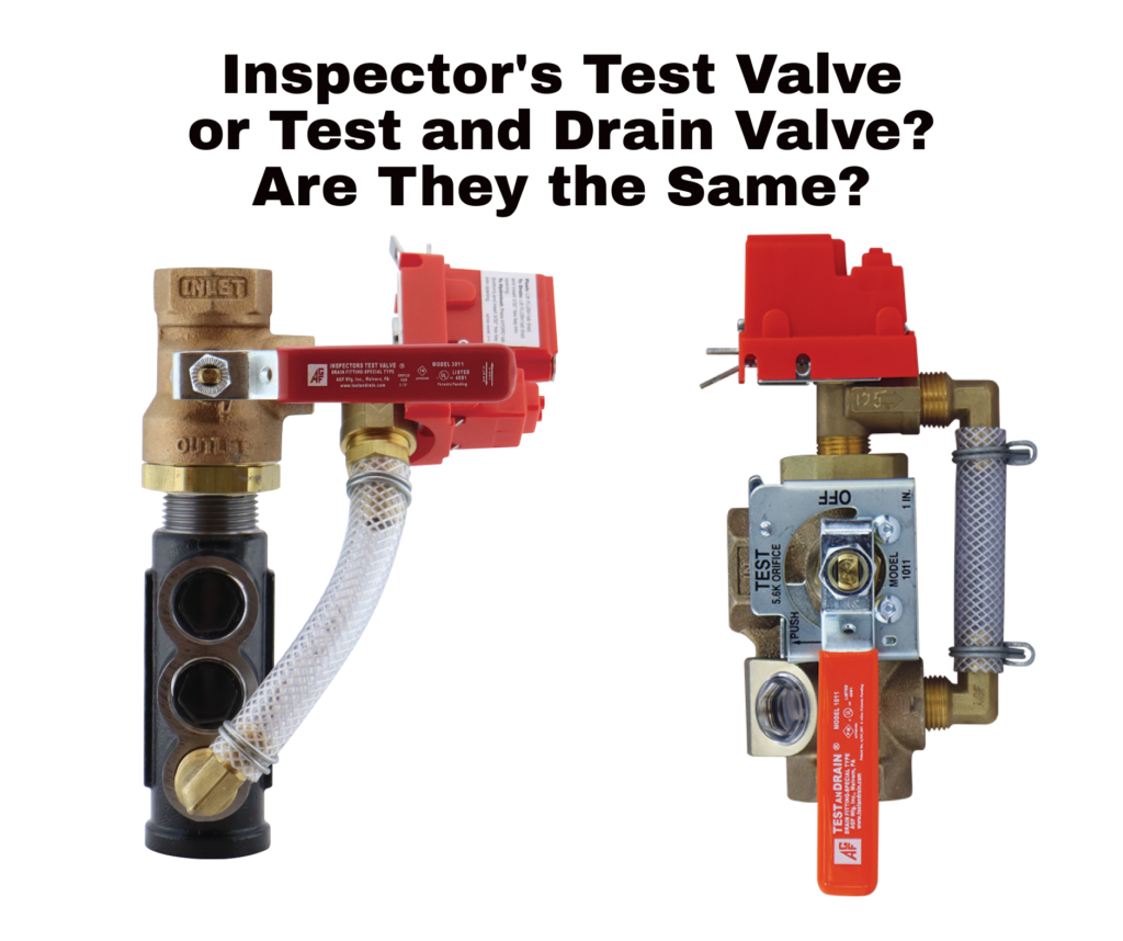
to meet code requirements. The Inspector’s Test Valves and Test and Drain Valves are frequently confused. This is because they perform similar functions but have distinct characteristics and applications. Understanding the differences between these valves is crucial to ensure their proper usage.
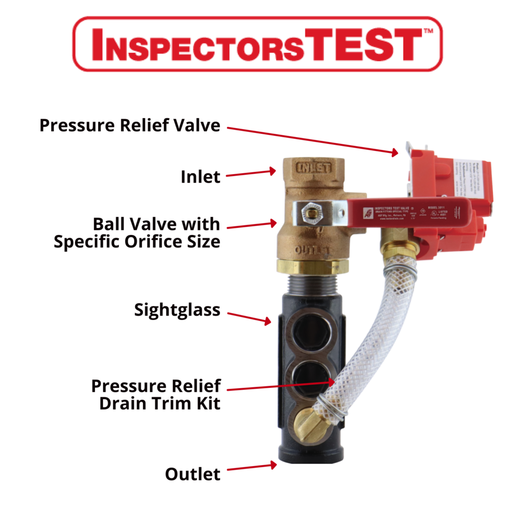
What is an Inspector’s Test Valve?
Parts of the valve
- Single-handle ball valve with a specified k-factor orifice to simulate the activation of one sprinkler head.
- You use a sight glass to visually confirm the flow of water during testing.
- Inlet and Outlet where the minimum 1-inch pipe connects to the valve. Water must flow in the inlet and discharge through the outlet.
- You can install optional pressure relief valves and trim kits on the Inspectors Test to fulfill the NFPA requirements.
Function
- The Inspectors Test Valve is designed to perform the NFPA 25 required sprinkler system’s alarm or water flow device. They can also test the opening of a dry or preaction valve during a partial trip test. During a full-trip test, they are utilized to test the water delivery time from when the valve is opened until the arrival of water to the furthest point in the system.
Location
- On a wet fire sprinkler system, Inspectors test valves should be placed downstream of the water flow alarm, which could be at the sprinkler riser or remote from the riser. Some jurisdictions have requirements or preferences to locate the inspector’s test remotely from the riser, so this is at the discretion of the AHJ.
- For efficient testing, FM Global (FM Global 2-0 2.6.5) requires the installation of the Inspector’s Test Connection in an easily accessible location. Also, ensure that it’s capable of handling the maximum expected water discharge and has an orifice that matches the smallest orifice size of any sprinkler within the connected system. Connect the Inspector’s Test Connection to the sprinkler system using piping with a minimum diameter of 1 inch (25mm) but not larger than the smallest branch line pipe in the system and don’t forget to attach an identification tag.
- NFPA 13 also requires valves to be accessible and no more than 7 feet above the finished floor. This requirement therefore makes them poor air vents on wet systems.
- Dry and preaction systems should have the inspector’s test valve located on the end of the most distant sprinkler pipe for each system.
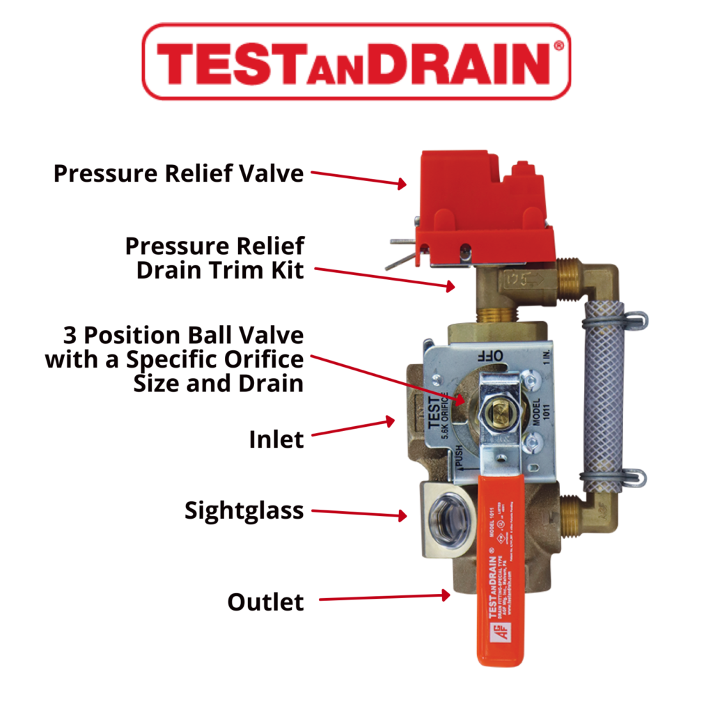
What is a Test and Drain Valve?
Parts of the valve
-
- AGF designed the first single-handle ball valve with three settings; off (closed), drain, and test. The internal ball has a specific K-factor orifice to simulate the activation of one sprinkler head when the handle is turned to test. The drain setting turns the internal ball to a secondary full port orifice used to quickly drain the system.
- The integrated, tamper-resistant sight glass confirms the flow of water visually during testing.
- The valve also has a ½” system access port for an inspector’s pressure gauge.
- Inlet and Outlet where the valve connects to the system. Water must flow in the inlet and discharge through the outlet. Installing this valve backward is a common mistake, although it may seem obvious.
- AGF’s Test and drain valves are available with optional pressure relief valves and trim kits. AGF’s valves offer flexibility by providing a port on either side to connect the trim kit. The unused port should be plugged using a 1/2″ brass plug. Please do not use the plastic thread protectors used for shipping on an active system.
Function
- AGF developed the Test and Drain valves to simplify installation by cutting extra components of the traditional loop assembly. It also replaces potential leak points and saves considerable space.
- Unlike an Inspector’s Test, the Test and Drain can also serve as the main drain on a wet system or zone control assembly.
Location
- Minimal requirements for the placement of the test and drain valve exist. It must be in an accessible location and be downstream of the water flow alarm. The drain must also discharge the drain water outside or to a location that will not cause water damage.
- Often test and drain valves s are located at the riser or floor control assemblies.
While both valves simulate water flow through a sprinkler, their internal mechanisms differ significantly. The Test and Drain Valve has a separate drain option for quick system draining. Understanding these nuances is crucial for proper installation and compliance with fire safety regulations. Choosing the right valve for the specific requirements of a sprinkler system can ensure efficient testing, maintenance, and functionality during emergencies. If you need assistance selecting the correct valve, AGF’s technical support is available. Please call 610-240-4900 or email techsupport@agfmfg.com.