Save Time, Save Water…Save Money
In 2010, NFPA 13: Standard for the Installation of Automatic Sprinkler Systems adopted the new standard requiring the installation of pressure relief valves on all wet systems. Prior to 2010, pressure relief valves were only required downstream of pressure reducing valves and on gridded systems.
The Requirement
In accordance with NFPA 13 (2010 edition – Sec. 7.1.2), and as maintained in every edition since*:
“…a wet pipe system shall be provided with a listed relief valve not less than 1/2 in (15 mm) in size and set to operate at 175 psi (12 bar) or 10 psi (0.7 bar) in excess of the maximum system pressure, whichever is greater.”
However, “where auxiliary air reservoirs are installed to absorb pressure increases, a relief valve shall not be required.”
Defining a System
It should be further noted that Chapter 3 of NFPA 13 (2013 & 2016 editions) goes to great lengths to define a system.
Section 3.3.22 (2013) and Section 3.3.23 (2016) define a sprinkler system as:
“a system that consists of an integrated network of piping designed in accordance with fire protection engineering standards that include a water supply source, a water control valve, a waterflow alarm, and a drain.”
Also, NFPA 13 Section A.3.3.22 (2013) and Section A.3.3.23 (2016) expand on Chapter 3’s definition further:
“as applied to the definition of a sprinkler system, each system riser serving a portion of a single floor of a facility or where individual floor control valves are used in a multistory building should be considered a separate sprinkler system. Multiple sprinkler systems can be supplied by a common supply main.”
The Bottom Line
The bottom line is that one must install a relief valve downstream of any control valve. Typically, that’s one on every floor of a multistory building that a single riser supplies. Or, it’s two where the total square foot area of the floor requires two supply risers).
This requirement intends to prevent pressure build-up from exceeding the working pressure of system components. Traditionally, the working pressure is 175 psi (12.1 bar).
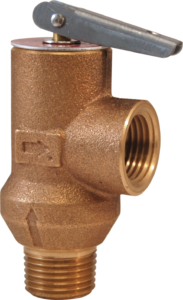
Relief Valve Rating
The pressure rating of the relief valve indicates an operating range of pressure for both the opening and closing of the valve. UL and FM standards for sprinkler system pressure relief valves require they to operate within that range.
FM requires a relief valve to OPEN at a pressure no less than 85% of their rating and UL requires OPENING at a pressure no greater than 105% of their rating. Both standards require the relief valves to CLOSE within a percentage below OPEN.
To choose a the right relief valve, compare static pressure against the rating. Compare static pressure to 90% of the relief valve’s rating to determine the estimated minimum OPENING. Compare to 80% of the relief valve’s rating for approximate maximum CLOSING.
Install the relief valve where it is easily accessible for maintenance. Take care that the relief valve CANNOT be isolated from the system when the system is operational. A relief valve should NEVER have a shutoff valve or a plug downstream of its outlet.
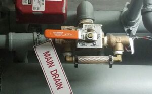
Relief Valve Location
One can locate the relief valve anywhere on the system. But, one of the most common and convenient locations is at the floor control assembly.
By installing the relief valve in this location, contractors are able to take advantage of the close proximity of a drain riser. So, the safe draining of the relief valve is easy to accomplish.
Industry professionals designed products specifically for this purpose. They have a convenient place to install a pressure relief valve and its drain line, including:
-
-
-
- AGF’s TESTanDRAIN® Valves
- AGF’s Inspector’sTEST™ Valves
- AGF’s RiserPACK™ Floor Control Assembly
- Viking’s EASYPACK Commercial Riser Assembly
- Victaulic’s® Testmaster™II Style 720 and Series 247 FireLock Zone Control Riser Module
- Tyco’s Riser Manifold, the Reliable CR Commercial Riser Manifold
- Guardian’s 9225 and 9230 Assemblies
-
-
Save Water/Save Time
During the installation process, a system needs to be integrity tested. One does this by pressurizing the system, typically to 200 psi.
However, it’s impossible to pressurize a system with a properly working pressure relief valve. It won’t allow the system to reach suitable pressure above the intended working pressure.
In order to confirm a leak-free system, it’s necessary to first install the system without the relief valves. Or, one can remove the relief valves before testing.
Install Before Testing with Lockable Pressure Relief Valves
AGF introduced a lockable pressure relief valve to avoid that process. Use a common hex wrench to temporarily lock the Model 7000L relief valve closed for testing.
Save time and install it with the rest of the system. Then simply lock during testing and unlock when testing is complete. This saves time, water, and money in the installation process.
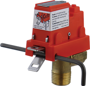
Install After Testing Without Draining the System
Many still need to install a basic pressure relief valve after integrity testing. AGF and Viking offer solutions unlike other products to make this easier.
The entire AGF TESTanDRAIN line and the Viking EASYPAC (built with the AGF TESTanDRAIN 1011A) allow for the installation of pressure relief valves without completely draining down the system.
While some water is lost when users use the drain position to isolate the installation port. But, it’s a small amount compared to the water lost and time wasted completely draining a system.
Plus, replacing an old or damaged relief valve is easier too. Complete the simple process without even removing the TESTanDRAIN from the line. That saves even more water, time, and money.
For more information or a quote on AGF products, find a distributor that serves your area.
*Requirement section number changed to 8.1.2 in the 2019 & 2022 editions of NFPA 13.
![]()
A version of this article was originally printed in the February 2017 edition of Fire Protection Contractor Magazine.